PWM Speed Control of DC Motor Using Microcontroller Circuit Diagram
PWM Speed Control of DC Motor Using Microcontroller Circuit Diagram In this project, I will show How Speed Control of DC Motor can be implemented using 555 and Pulse Width Modulation (PWM). We use DC Motors in many systems in our day to day life. For example, CPU fans, fume extinguishers, toy cars etc. are all DC Motors which are operated by DC power supply.

Learning DC motor speed control with PWM using Arduino opens up endless possibilities for applications in electronics, robotics, and automation. By understanding how PWM works, choosing the right components, and writing efficient code, you can build reliable and adaptable motor control systems for your projects.
How to Use Pulse Width Modulation (PWM) in Motor Control Circuit Diagram
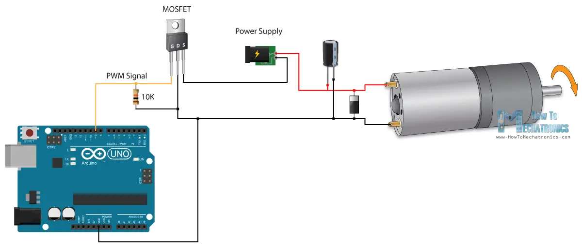
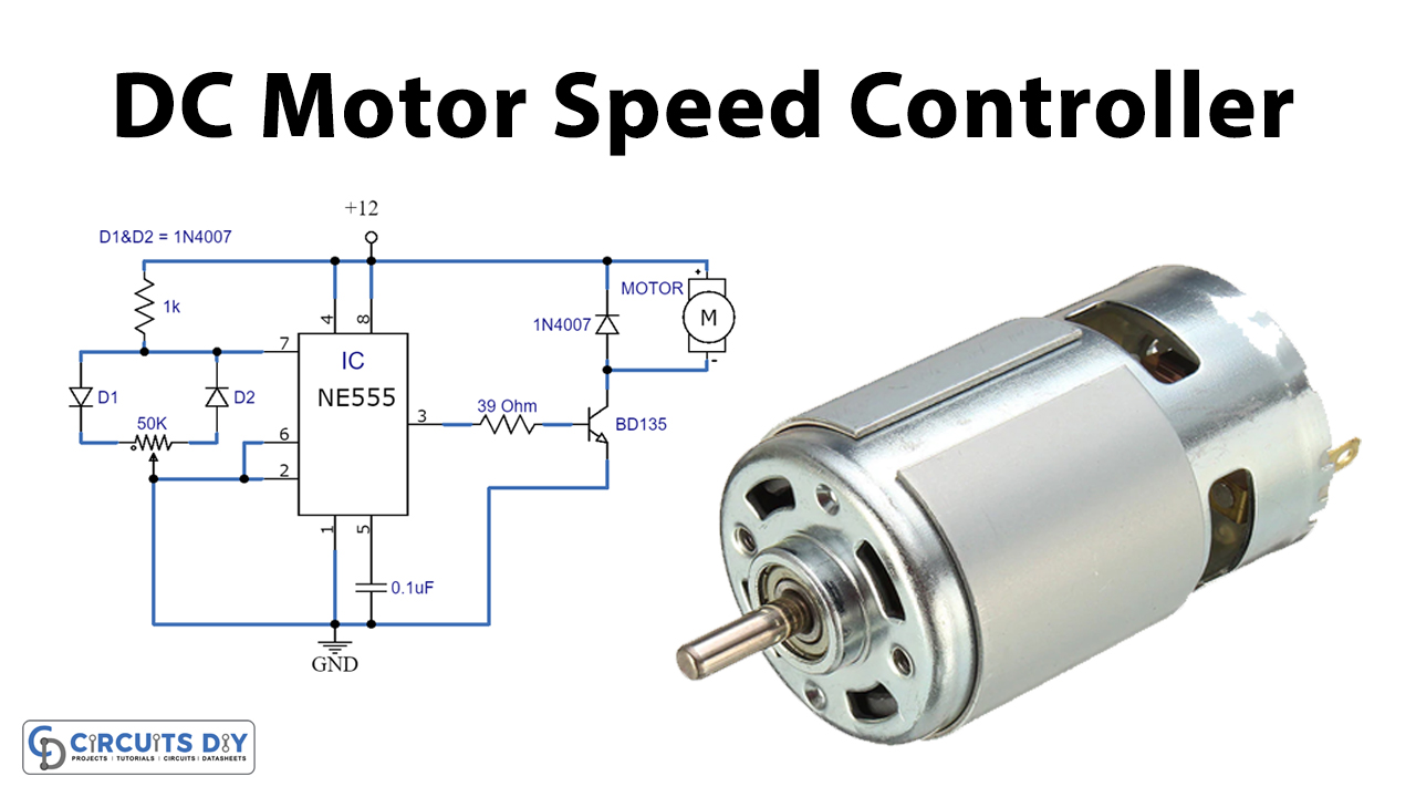
By adjusting the length of the ON/OFF pulses, we can set the voltage to anywhere between 0V and the maximum voltage. We will use this PWM signal to power the motor directly. PWM Motor Driver. There are several ways to generate the PWM signal for the motor, but in this tutorial we will use the 555 timer. Here's a schematic of the circuit: Small DC motors ideal for use in applications where speed control is required such as in small toys, models, robots and other such electronics circuits. A DC motor consist basically of two parts, the stationary body of the motor called the "Stator" and the inner part which rotates producing the movement called the "Rotor". Setting Up the Basic DC Motor Control Step 1: Connect the Components. Hook up your Arduino Uno to the breadboard. Connect the DC motor to a PWM-capable pin (e.g., pin 9 or 10). Add a flyback diode across the motor terminals for safety. Step 2: Arduino Code for the PWM Signal. Here's the Arduino code snippet to control motor speed:
How to control DC motor speed using PWM on Atmega32. Using PWM (Pulse Width Modulation) to control a device is a common practice in embedded systems; for example, you can use it to control the light intensity of a LED or control the speed of a DC motor. In this article, we will explain how to get a PWM from the AVR Atmega32 and we shalll apply

Speed Control of DC Motor Using Pulse Width Modulation Circuit Diagram
Controlling the speed of a DC motor while simultaneously monitoring its current consumption is an essential aspect of many robotics projects, motorized systems, and energy-efficient applications.In this tutorial, we'll walk you through how to control a DC motor using PWM (Pulse Width Modulation) and measure the current drawn by the motor using the ACS712 current sensor with an IRF540N MOSFET Applications of PWM in Motor Control. DC Motors: PWM adjusts the speed and direction of DC motors in robotics, drones, and home automation systems. Servo Motors: PWM signals determine the position of servo motors, commonly used in robotic arms and pan-tilt systems.
