Operational Amplifier Active Low Pass Filter Circuit Diagram
Operational Amplifier Active Low Pass Filter Circuit Diagram View full article: https://www.allaboutcircuits.com/video-tutorials/op-amp-applications-low-pass-and-high-pass-active-filters/In this video we will explore a

When used like this in audio applications the active low pass filter is sometimes called a "Bass Boost" filter. Second-order Low Pass Active Filter. As with the passive filter, a first-order low-pass active filter can be converted into a second-order low pass filter simply by using an additional RC network in the input path. The frequency Step-by-step design of Active low pass filter using Op Amplifier.

Pass Active Filters Circuit Diagram
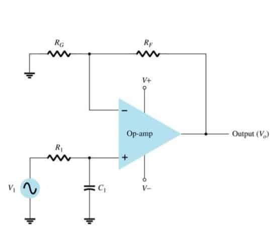
The basic configuration for an active low-pass filter using an operational amplifier is as follows: Place the operational amplifier (op-amp) on a breadboard. Connect a resistor (R) between the input signal source and the non-inverting input ( V in ) of the op-amp.

Second-Order Active High-Pass Filter. If we swap the resistor and capacitor in an RC low-pass filter, we convert the circuit into a CR high-pass filter. We can then cascade two CR high-pass filters to create a second-order CRCR high-pass filter. If we incorporate this passive configuration into the Sallen-Key topology, we have the following:
PDF Active Filter Design Techniques Circuit Diagram
Active Low-Pass Filter Design Jim Karki AAP Precision Analog ABSTRACT This report focuses on active low-pass filter design using operational amplifiers. Low-pass filters are commonly used to implement anti-aliasing filters in data acquisition systems. Design of second-order filters is the main topic of consideration.