32 Operational Amplifier Circuits Circuit Diagram
32 Operational Amplifier Circuits Circuit Diagram feedback op amp equations, and they teach the concept of relative stability and com-pensation of potentially unstable op amps. Chapter 8 develops the current feedback op amp equations and discusses current feedback stability. Chapter 9 compares current feedback and voltage feedback op amps. The meat of this book is Chapters 12, 13, and
The name "op amp" is the standard abbreviation for operational amplifier. This name comes from the early days of amplifier design, when the op amp was used in analog computers. (Yes, the first computers were analog in nature, rather than digital). When the basic amplifier was used with a few external components, various mathematical
PDF A Current Feedback Op Circuit Diagram
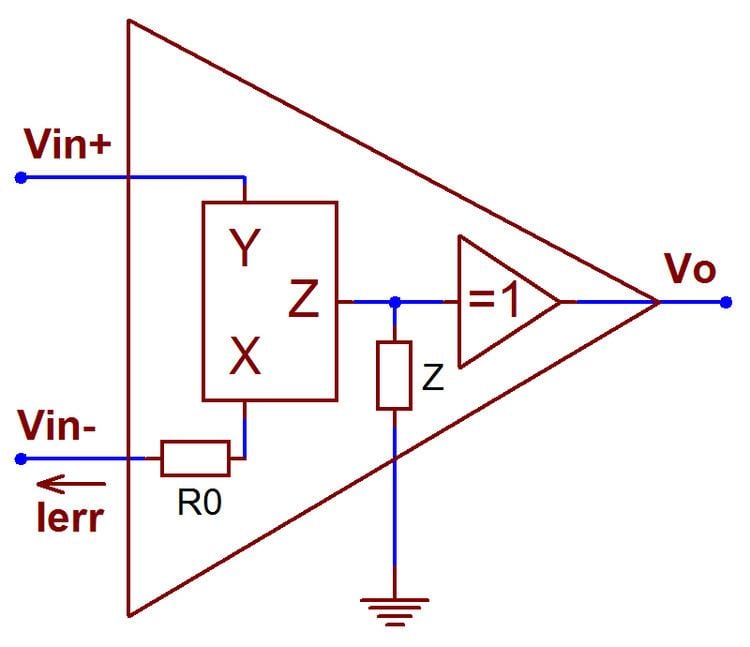
determines the voltage gain in current-feedbackop amp circuits. With current feedback, however, dynamic performance is largely independent of the voltage gain. (See AN-300Simple Circuit Detects Loss of 4-20 mA Signal (SNOA605) for a technical discussion of current-feedback.)Also, the optimum feedback
Practical Current Feedback Amplifier Design Considerations The current-feedback (CMF) amplifier is a fundamentally different approach to high-frequency gain blocks. Not just an input stage, it is a full amplifier topology. It has outstanding characteristics in several areas: very high slewrates, -3dB bandwidth which is almost constant with Current feedback op amps do not have a fixed gain-bandwidth product. Figure 4: Current Feedback Amplifier Frequency Response . Gain is manipulated in a CFB op amp application by choosing the correct feedback resistor for the device (R2), and then selecting the bottom resistor (R1) to yield the desired closed loop gain.

PDF CHAPTER 1: THE OP AMP Circuit Diagram
Current feedback amplifiers are used in broadcast video systems, radar systems, IF and RF stages, RGB distribution systems and many other high speed circuits. As with any new circuit, there are several new rules that must be kept in mind to prevent problems. Because current feedback amplifiers act very much the same as regular op amps, it is 8 A Current Feedback Op-Amp Circuit Collection Appendix A Current Feedback Amplifier Stability Model To understand why a current feedback amplifier must use a recommended value of Rf, it is necessary to delve deeper into feedback theory. Figure A−1 shows a general feedback model, which consists of an input voltage V IN, a